Thursday, April 28, 2016

Scaled Experiment Metrics and Development Pathway

Stability remains an issue - it is one of the core weaknesses of the proposition for the gravity balloon concept. The issue isn't whether the fundamental principle of laminarization will work, or even necessarily that the channel flow physics are suitable for this problem, but the behavior of a complex and fairly high-energy system.

If you took a simplistic picture of the wedge effect, the prediction would be a slight restorative force for each layer of the friction buffers. The exact directionality of this force gets complicated. It gets even more complicated by the non-rigid nature of the buffers. What we should really raise our eyebrows at, however, is what happens when you consider all the numerous sheets in tandem. Loosely connected dynamic systems can be prone to failure, and this situation seems like a candidate for that. But then again, maybe not. The solution becomes fairly non-trivial.

Due to the complexity of the problem, our only best option left is to perform scaled experiments. Ideally, we would like to use a fluid that is more convenient, in that the same flow patterns can be produced at a smaller scale. To do this, we will look at the Reynold's number.

Re = rho v d / mu

We would like something with a high density and a low viscosity (in particular, relative to air). It becomes fairly obvious that water is our best option for this. Also, you can see that we have 2 dimensions over which to flex our abilities - that is the velocity and the distance metric. Now it seems pretty clear that we want the smallest structure that we can spin at workable speeds.

These 2 degrees of freedom would still dictate a massive scale of experiment, if taken to apply to the entire system all at once. By that, you can say that d is the diameter of the outer-most friction buffer (for example), and that the system will be a scaled model in terms of all geometric dimensions. The enormous cost of this nudges us to seek cheaper solutions that might go 80% of the way with 20% of the effort. In a more accurate accounting, I'm looking for something more like 10% of the ultimate discoveries with 0.001% of the effort.

Obviously, we might instead take d to measure the distance between sheets, while also relaxing the requirement for strict geometric similarity. This might be nice in order to make something testable by reducing the number of sheets compared to the gravity balloon reference design. Thus, the overall scale and velocities will be dramatically less, while still demonstrating channel-to-channel interactions with the same flow patterns.

This still won't be sufficient to make an immediately tenable experiment. We'll need to relax something related to the channel flow pattern itself. The obvious candidate is to change the channel width relative to the overall tube diameter. However, I will not count this as an independent variable, because I think that (for most cases) it will fall out of the selection of the number of sheets. In any format you choose, it's likely that the ratio of the overall thickness of the friction buffer region will be about 50% of the tube radius. So greater channel width will follow with fewer sheets.

Our hypothetical experiment has been cut-and-slashed a lot by this point, but we're not finished yet! What is truly the really important point? What would we want to learn from this? I would argue that it is the interaction of multiple friction buffers in a (generally sufficiently) turbulent flow regime. Even if you cut that out, there's still some value because it answers some questions about this broader notion of friction buffers (which can even have other applications). However, we do want to answer questions about the friction buffers used in a gravity balloon regarding their stability. We basically know that the answer will be different for laminar and turbulent (or at least somewhat independent). Let me illustrate my thinking in a sketch.

(let me volunteer that I know I illustrated the transition region poorly)

Basically, we want to probe on the minimum edge of turbulent flow regimes with a multi-sheet friction buffer system. Just opt for an outright change of Reynolds number according to the abilities available for experimentation. This would be the 10% of ultimate knowledge I'm interested in. This would set the stage for everything that may (or may not) come in the future.

The good news - all this slashing of the metrics gets our experiment size way down (the scale is highly sensitive to Reynolds number). And that gives us some wiggle room. With lower Reynolds number, we can play around with more sheets (even up to 10 or 16 as I'm dreamed about), while staying at least in the turbulent regime. With the same general equipment, dial the numbers the other direction, and see about higher Reynolds number channels with fewer sheets.

Once you start chewing on this, something new starts to take form - a general format of the development path. Because as these numbers are dialed back up to the full scale (with more resources), its possible to speculate when many different components of the design will be proven in principle. After that, you can image at what point those components will mature into a representative suite of technologies. For instance, at certain numbers, the intra-sheet flow management will become testable. At another point later on, active controls for maintaining the seals could be strapped on.

So now we've covered 4 (mostly) independent factors. I think this is probably the right way to look at scaling of real, physical, experiments. These can start on a household scale.

Wednesday, April 27, 2016

Illustrations of the Friction Buffer Tapers

This is a fairly simple illustration of the problem that we start out with. The friction buffer concept was conceived of essentially within a cross-section of a gravity tube and the surrounding sheets. As the ends of the tube's hull is pinched, so must the friction buffer sheets as well. The problem comes down to how we manage the geometry of the sheets in this area, as well as how we make the moving connection.


Two solutions have presented themselves as relatively strong candidates for an ultimate solution. They both have a similar pattern to them. The sheets pinch in with both ideas, but in the "zero" solution they terminate against the next-inner-most sheet, while in the "nested" solution they terminate against the hull itself.

Here is a quick sketch of the taper-zero solution. Keep in mind that this is 1 quadrant of what is illustrated in the above problem sketch.


Here is a quick sketch of the taper-nested solution. The calculation for the connection points is different from the taper-zero, and this causes the connections to happen at small radii, and possibly face higher velocities at the connection points. An advantage is that connecting to the hull is probably easier, since it is a hard surface.


For the connections themselves, I envision a tensile tensioner acting at the end of the sheet in order to control the clearance and positioning of the sheet. This applies for both of the concepts.


Hope these were fun to look at. I'm not much of an artist, but since the hand-drawn sketch is a popular style these days, I figure "why not" and avoid the tedium of creating these on a computer.

Friday, April 22, 2016

Introduction of "Taper-Nested" Friction Buffer Connection Scheme

Suffice it to say that a minimum viable case has been made for the engineering of the friction buffer connection points. However, the very day after I claim to have "solved" that problem, I noticed that another scheme is possible, and possibly even better. I will make this post as a brief introduction, and I apologize for the painful lack of illustrations this leads to.

Let me clarify the naming - the names refer to whatever kind of logic sets the pressure around the (moving) connection points (seals). You can see that this, combined with the velocity constraint, forces all of the other parameters to follow suit. That's why this taxonomy makes sense. In the taper-zero scheme, all seals were approximately at ambient atmosphere pressure. Note that all friction buffer sheets are at a slightly positive pressure in order to maintain their shape with a controlled leakage, and this extra positive pressure is not accounted for directly in the math (partly because there is no lower-bound, and partly because it may be small enough to neglect).

Imagine, instead, that the seals connect to the tube itself. It's irresistible to call this the "hull" of the artificial gravity tube. The interior is obviously where people live, but the exterior may be just a metal wall. Picture connection points all along the sloped part of the hull. There are 2 options for how to determine the spacing between those connection points:
  1. Constant distance between each connection
  2. Setting connection location based on a invariant relative velocity limit
Once I ran a few numbers, it quickly became clear that option #2 leaves the majority of the connection points clustered very close to the end opening (at small radii to minimize the velocity difference between the sheet material and the faster rotating tube). After chewing on this a bit, I find that this sets the stage for the central engineering tradeoffs for the friction buffer connection engineering.

Engineering Showdown between Solutions


Taper-zero connects sheet-to-sheet. This taper-nested scheme connects sheet-to-hull. Making the connections to the hull will give better predictability and stability, because the other sheets and highly deformable. The advantage of the taper-zero approach is that the relative velocities at the connection points are very slow and consistent, while at the same time they are evenly spaced and open to atmosphere for maintenance.

Now compare to the taper-nested approach. This scheme puts each friction buffer sheet fully inside of the next outer-most one. Getting to that connection to do service work on it will be much more complicated. Also, they will require awkward clustering toward the end if the relative velocity is kept constant. Alternatively, we can assume the constant distance spacing, and we find that the connection points have variable, and often quite high, relative velocities. This is riskier (but might be preferable with the advantage of the stationary hull), and it also imposes a meaningful air drag penalty. The additional air drag may be partially compensated for by increased spacing between sheets compared to the radially symmetric portion.

We're not done yet. Recall the central concession of the taper-zero approach - that the friction buffer sheets must have substantial material strength. This is partly to compensate for the radial acceleration of the air in its region, but mostly as a design tweak to keep the seal at close to ambient pressure (thus the "zero"). For the taper-nested approach, leakage air is recycled from one stage to the next. That means that the sheets connect at a pressure which is already higher than ambient due to a non-zero radius. In taper-nested, you wouldn't strictly need holes in each sheet to allow ingress into the next stage, because the loss from one stage is also the loss for the next-most stage.

My initial hope was the the material strength of the sheets would be lowered in the taper-nested scheme, but so far I have not been able to nail this feature down, and it could go either way. Jury is out on that topic. It is also not obvious that one is simply better than the other, and I may be hedging my bets between the two for quite some time to come.

Thursday, April 21, 2016

Artificial Gravity Tubes with of the Mashveya World with Friction Buffers

There are now honest-to-god friction buffers being utilized in fiction and world-building. Check it out at:

http://accelerando.tumblr.com/

This author illustrated the tethers used to spin up a tube, as well as a buddy system for spin maintenance. For future reference, here is one post that contains both pieces of content. This has a great deal of technical accuracy. You can see in the axle mount system (buddy system) that there are trusses necessary to handle the varying compression / tension action with changing the direction of angular acceleration.


The world these designs exist in is called Mashveya, and uses transportable fuels (like hydrocarbons) for their energy economy, so these are free floating and exist in a smoke-ring type world with a fairly low density of habitation. I find this image with additional world context quite stunning. Calling this a catamaran system makes a lot of sense.


Quite a few possibilities jump right out at me. Many different methods of navigation would be possible. You could use some flow control to direct air out one end to power flight in the axial direction. It would even be possible to fly perpendicular by allowing the outer-most sheet to spin freely, and blocking flow around the middle portion or on the two sides. I might diagram some of these later. These are extremely cool. Seeing these brings an entirely new perspective to some of the underlying concepts.

Wednesday, April 20, 2016

The "Taper-Zero" Design for Friction Buffer Tapering and Pressurizing

Gravity balloons, with friction buffers to allow artificial gravity inside them, have so-far had one major design aspect missing. There are a few reasons for this. Partly, it was an non-intuitive problem, and every time I returned to it, I started out going down the wrong track with a careless sign error somewhere in there. Another reason is that it's genuinely a hard problem. But the main reason it has taken me so long to present a full solution is because I didn't want to accept what the math was telling me. Up until this point, I have always wanted to imagine the friction buffer sheets as something with a zero-thickness limit - something that could be literal paper, aluminum foil, or some other absurdly thin material. This was unrealistic and didn't fit with the other basic realities of the turbulent reference design parameters. I also resisted a 2nd obvious design decision, which was to have the moving seals connect sheet-to-sheet as opposed to sheet-to-center-line-structure. I may go into those trains of thought, but in this post I mainly want to communicate the bare minimum to lay out this design.

The problem is how to "terminate" the friction buffer sheets. For the bulk of an artificial gravity tube, there is radial symmetry, so the problem is relatively easy to envision. The fluid flow between sheets is very nearly approximately a parallel sheet flow problem. The basic mechanism to reduce friction is flushed out in the radially symmetric form. Intuitively, it seems "messy" to picture how the sheets pinch at the end, similar to the tube itself. No matter what specifics you opt for, this also introduces a moving seal, at which point an engineer may think "yuck", but still accept that there's no choice but to deal with some seals. We take comfort in the fact that, while the seal length is large, it is at low speeds and low pressures. The problem that really blows down the house of cards is the realization that, as the sheet pinches to the contact point, the air pressure in its volume decreases - and that different layers decrease at different gradients.

I've summed up some details of this problem space in the last post and at other times in this blog. So here I want to jump right into the solution space.

The Solution Space


A design solution starts by holding something specific constant, and then fills in the rest of the values from there. I will name the different solutions according to that assumption. The first intuition I had was to terminate all friction buffer sheets very close to the tube's end opening, which I will call the taper-center design. This is still a possible solution, but I believe it's inferior due to the complications of making the seal act between the flexible sheet and the stationary connection point around the tube ending.

As I came to better understand that the pressure distribution within the friction buffer region would be a problem (at all), my natural intuition was to imagine that there is no pressure difference over the radially symmetric part of any of the friction buffers. I would call this the sheet-isobaric solution method. This start with the assumption that we will preserve the "no strength" requirement for the sheets, and figures out where to go from there. The problem comes when you pinch in toward the end opening - even the slightest bit. The pressure drops as you decrease radius, but the real kicker is the fact that pressure drops (a) below micro-gravity ambient and (b) faster for the innermost sheets. This means that in the taper region the sheets will be "sucked" in towards the tubes. Combating this would require complex, rigid, and moving parts. I hate all 3 of those adjectives! The fact that the sheets can't passively maintain their shape if they don't have a positive pressure is what I will call the convexity-constraint. How often do you see a balloon with sharply convex shapes? Never, exactly. Now, the balloon notion here is different from that of the overall gravity balloon. But for simplicity of operation, we all but demand that the friction buffers act sort-of like a balloon so that they don't need rigid members. Moving on, why does this constraint create any problems? Why do we need to taper (pinch at the end) the sheets at all? Why can't we just terminate them against a rigid structure at the radius they start out at? Because that would demand a moving seal at > 100 mph, and defeat most of the purpose of the friction buffers in the first place. This is what I will call the velocity-constraint.

Maybe we can come to something of a compromise here, and now we arrive in a design space that I found to be a large bit of a pitfall myself. I imagined the sheets terminating against a rigid structure that fanned out from the end opening. This increases the radius in a graded system, and thus largely avoids the velocity-constraint. I might call this the center-graded deign, and it has some neat properties, but those properties wound up being largely irrelevant to the problem. These configurations just couldn't save us from the convexity-constraint. By connecting to a seal with a rigid structure at low radius / low velocity, you are still going to run into that sucking problem and have to use a massively expensive system to partially pin the moving sheet to the rigid structure. I struggled in this logical knot, trying to somehow make the pressure gradient turn around in my mind. Alas, when you rotate stuff, it wants to fling outward. Fighting that is a fool's errand, and tension is better than compression by 10x factor or greater.

So let's move on to accept taper-zero hypothesis and design. The cold logical facts are telling us that the friction buffer sheets (1) are concave geometries (2) must have positive pressure compared to ambient and (3) must have positive pressure relative to the next outer-most sheet. This is a mouthful, it is weird, and it sacrifices some of the most beloved assumptions up until this point. I believe there is a logical train of thought directly from these principles (hard-fought conclusions from the previous failed design spaces), and I will probably not do that train of thought justice here, and I will be skipping some. But the final insight is pretty cool.


A combination of two, and somewhat a 3rd one, factors suggests that we don't connect the sheets (moving joint) to a rigid structure, but instead to each other. Those are the convexity-constraint and the velocity-constraint together. We want the outer sheet to connect at large radius (velocity, combined subtly with a desire to keep strength requirements low), but we also want to keep the friction buffers "puffy". We wind up with a vision of one puff puffed out on the outside of another puff. Now, for pressure, this suggests that the connection between the puffs is just a little bit higher than ambient. This directly suggests what the pressure of each stage will be like (assuming you have values of radii for connection points, which you can just get directly from the velocity constraint).

Taper-Zero Design Specifics


Each sheet connects at a different radius - smaller radius for the innermost sheet, and large radius for the outermost sheet. The exact picking of connection points can be engineered to your own desire. Here, I'm going to be using the velocity constraint to have all sheets move at the end-opening speed at their connection point. I'm using 10 sheets in this reference design, because 16 (a previous benchmark) is just too labor intensive to illustrate.

These sheets will actually have a pressure at some minuscule value over ambient at the seals, and they will be constantly leaking air (I'll talk more about this later). Additionally, there will be no complicated system maintaining the pressure and position. Instead, the 2 ends of the friction buffer sheet will have a simple remote-controlled tensioner unit which can increase or decrease the clearance distance (thus impacting the leak rate and the pressure).

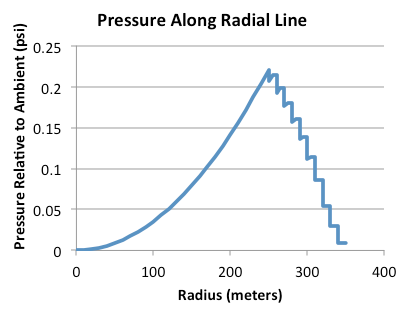
Start from the seal, and move outward toward the center of the channel in the radially symmetric portion of its geometry. The pressure increases, depending on how fast that stage is rotating. The ultimate pressure in the channel is almost entirely a consequence of the rotation speed of the stage. Next, observe that inside of the channel there is some radial pressure gradient, but the sheet is also holding back some amount of air pressure as well.

I don't know if this fully illustrates it, but it is an attempt. This graph is telling the story for each stage, going from the connecting point (venting air to atmosphere) to the channel interior.


Next, let's look at the profile as you increase radius from the center-line in the center of the tube. You can't literally traverse this path, and this is just an illustration. The tube itself has a pressure increase from ambient, dictated by its rotation. The innermost friction buffers mostly inherit these same numbers.

The big point I want to make here is that the friction buffer sheets are fighting the radial gradient of air pressure. In the 2nd graph, you can also make note that the saw-tooth looks different. The "step" part of it has a slope to it that the outer layers don't share. This is because the inner layers are rotating faster. That shows the presence of a strong radial air pressure gradient toward the inner-most layers compared to the outer layers that are most stationary.

Air Flow


The floor of the artificial gravity tube, and the sheets themselves, would have holes in them. Not a huge number - there is no obvious lower limit. The inner layers would have more holes than the outer layers, because air must flow through them all to get to the outer layer while ever layer loses about the same amount to leakage.

In this scheme, while the air flow percolating through the layers can be actively controlled, it is not necessary. It would be more simple and still effective to just operate the tensions that control the leak rate along the seals, and these would be tremendously simple seals.

In retrospect, abandoning the dream of zero-strength requirement sheets bought us a lot. It's that simplicity that I see coalescing the design where someone can put their foot down and say "yes, this all is consistent and coherent now". I still see possible improvements to this, but the important thing to note is that I see them all starting from this design as a template.

What's left to do? I need to revisit the impact of elasticity. It was never really an issue before now, but with the sheets holding back some quantity of air pressure, it will be relevant again. Trickier - it may change as the rotation rate changes. That demands some extra engineering of the seal actuation during spin-up and spin-down. Nothing crazy, I can already mentally picture a lot of the specifics. It's likely that the tube would have auxiliary compressors that will intentionally inflate the friction buffers while the tube is not yet rotating. Predictable movements in this phase of spin-up will give confidence to begin rotating the entire tube.

Monday, April 18, 2016

Runthrough of Friction Buffer Management Challenges

I have been long-overdue to share even some of the most basic thoughts I've had regarding specifics of the configuration of the friction buffers. To recap some basics, this blog describes open-air rotating tubes to create artificial gravity. The ends are pinched (to perhaps 1/8th or 1/10th the surface radius) with air flowing freely through the inlet and exits (aside from flow control clutter I've written about). The rotation can be maintained at a low energetic cost by multiple layers of sheets surrounding the tube.

Problems only become glaringly apparent when you combine all of these construction elements into a single package, and realize a component which was helpful in one respect is messing up the design in another respect that was hard to imagine. In particular here, I have in mind the combination of 1) the taper and 2) the friction buffer layers. The obvious conception is that the friction buffers (just like the ground itself) tapers up toward the opening. But this comes with hazards.

I don't mean to claim this is the only engineering problem within this general topic. However, I also want to stress that I see none of these inflicting anything close to a mortal wound. They are, for the most part, problems with foreseeable workarounds. I only intend to articulate how these workarounds constrain the design space. I will have to start by naming the problems in the first place

The Balance Problem


The inside air of a tube falls with radius from the center-line. This is true for any rotating artificial gravity habitat. The point I want to stress here is that we also have to think of this in the context of the friction buffers.

Let me get one thing straight - the relative rotation speeds of the friction buffers are dictated by the fluid mechanics. For complex geometries, you can't even predict this perfectly in advance.

Now if the air is falling in pressure because it is rotating inside the tube, then it is also clearly rotating between the friction buffers, but at a staged rate. So the math is different, but there's still a pressure gradient - and pressure falls as radius increases. Carry this to its logical conclusion and you'll arrive at a contradiction. Walk from the center-line to the outermost friction buffer, and the pressure goes down over the entire trip. But the center-line must be the same pressure you started with. The discrepancy is because the tube will act like a centrifugal pump if you let it. Our intent is to avoid that by implementing a barrier to the flow somewhere (as an absolute necessity).

Solutions:
  1. Maintain a pressure barrier as part of the outermost friction buffer, keep pressure drops over all other sheets (and the surface) small
  2. Maintain a substantial pressure barrier in the floor itself and allow the sheets to keep a small delta P from one to the next

The Taper Problem


This is the most critical and most interesting problem to me. It's also hard to explain. Start out the outer surface of the outermost layer of the friction buffers. The pressure drops as you go to lower radius. But (and here's the kicker), as you climb the taper at the end, the rotation rate drops too.

Firstly, this presents a problem that you will have trouble maintaining a positive pressure compared to the ambient atmosphere as you climb toward the end opening. Secondly, it means that the problem repeats itself for each layer of friction buffer compared to the next.

Why is this a problem? Consider a balloon (no word tricks here, a literal balloon). It has a positive pressure, and it maintains its shape because of that pressure. If some part of the balloon transitions to a negative pressure, what happens? That parts caves in on itself. That's the problem we are dealing with in the taper regions.

Solutions:
  1. Design the sheet-by-sheet over-pressure to be greater than the pressure change drop as it climbs the slope toward the end opening
  2. Implement the seals in a graded pattern outward from the end opening
I know this is getting hard to visualize. Here is a token attempt to sketch it. (please ignore the lines in the upper right, it's just too late to edit them out right now)


It's hard to keep in mind the speeds when you look at this. All friction buffers have about the same speed difference relative to its neighbor, and the outermost sheet is almost stationary relative to the ambient air. So this does not introduce any extraordinary speeds, because while the innermost sheet is moving fast, the taper brings it down to a manageable speed.


The Seal Problem


This is the most obvious of all - the connection between the sheets is a moving seal over a long distance, and this can easily get expensive. Solutions:
  1. Mechanical tracks to maintain the coupling and minimize the air ingress
  2. Passive ring that can be tightened dynamically to keep the clearance distance small
  3. Labrynth seals
Points #2 and #3 are mostly complementary.

My own vision is a combination like #2 for the balance problem, #2 for the taper problem, and #2 for the seal problem.

Monday, April 11, 2016

Small Balloon-Tubes Systems, a Gauntlet of Wires, and Sucking Sheet Pinches

This is a fairly general brain dump of a collection of topics. I could see them all being posts, but not all of them are likely to become posts, so I want to get them out while the concepts are fresh in my mind.

People-Units 


While working on the math for this stuff, I keep coming back to notions of "magic" numbers. There are very defined numerical parameters that we can spin our own abstract tapestry. What's most unique about this project is what defines those bounding parameters - they almost all come down to human biology. Why is a gravity balloon a certain size? Because humans need a certain pressure, and this combines with the _fundamental_ gravitational constant to produce a tangible number.

All this reminds me of the notion of "god" units, or Planck units. The fundamental units span the full range of physical values. Because of this, you can measure practically any complex quantity as a combination of the fundamental ones - like volume.

People units constitute a rougher and more gray set of fundamental constants. Combining the gravity people need with the air properties they need, you can get the characteristic height of Earth's atmosphere, but there are lots of other ways you can come up with different length units.

Minimum Size for Friction Buffers


Lately on NASA Spaceflight forms, I've seen artificial gravity inside of balloon envelopes come up. This has a rather strange similarity to what I've talked about in this blog. The motivations given for this design are predictable - space stations can continue to be thought of as a nice inertial frame of reference, like the ISS, while adding centrifuges in a limited domain. The basic idea is to take a large Bigelow module and put 2 counter-rotating centrifuges. The two can be spun up at the same time so they have minimal effect on the rest of the station.

The minimal effect principle is an objective very much worth pursuing. For near-term space stations, we will expect many roles to be fulfilled by the station, and external operations can not be compromised for the logistics of a spinning module. In this context, it's hard to imagine that anything other than a fully enclosed centrifuge can make sense.

But where does this lead us? Operationally, I can paint somewhat of a picture. If you moved around in such a centrifuge, vomiting seems inevitable. However, limited time spent for the purpose of maintaining health seems possible if you limit people's activities (and compare to the fact that they'll be feeling sick anyway). But what about drag? For something just a few 10s of meters, it's likely that you would leave the annular space alone between the centrifuge and the balloon wall. But at what size will it make sense to add any friction-reducing buffers? It depends on how much energy you're willing to put in, but it seems simple to compare this to the energy expenditure of other station systems.

That sounds like some pretty low-hanging fruit for developing a practical case for more investigation into this tech. Importantly, some push into this area would raise some obvious experimental pathways to establish the friction buffer sheet stability.

Scaled Experiments 


Stability of the friction buffers is a tough topic, so it makes sense to give up on the analysis and defer to experimental evidence at some point. Fortunately for us, the available fluids helps to make the problem easier for us. Air is a low density and low viscosity fluid. Water an extremely obvious stand-in for scaling based on similar Reynolds numbers.

I have two types of things in mind:

    sheet Reynolds number
    true scale model

You could scale the entire system of an artificial gravity tube by selecting an experiment geometry that is exactly similar to it but on a tabletop scale. In practice, however, this leads to sizes or speeds and torque that are just not workable. This could not be a tabletop scale experiment.

Instead, it will make more sense to emulate the separation distance and speed of the friction buffer layers, and see how the multi-sheet stability looks with different kinds of configurations.

Problem with all Center Connections
I misspoke somewhat in my previous post introducing transport of commodities. I had presumed that some commodities could be sent through connections that existed exactly on the axial line. This can not possibly be the case.

It is an easy mistake to mistake. You can simply imagine that cargo moving through the center can move slightly to the side of the axial line itself. The rotation speeds will not be substantial for a great distance beyond this, and the weight itself would not be overly burdensome. The problem comes when you realize that the rotating part... well... rotates. You can't simply move cargo to the size of the connection and move it along, because the line (pipe, wire, etc.) going to the colony rotates. If the cargo stalled inside of the plane that this line rotated in, then it would collide with the line.

This seems impractical in my vision of the economy. It would be far better to keep the center-line of artificial gravity tubes completely empty aside from rails which which cargo is moved along with. The challenges for connecting at a larger radius for power, water, information, etc. are completely solvable. Transit of bulk materials is much trickier, so the center line would need to be reserved for these activities.

Relative Movement of Tubes and Balloon


I must take some time to argue with myself on the subject of how the artificial gravity tubes move relative to the balloon "wall". The most simple solution is that they don't move. Actually, this is quite practical in terms of the inflation physics. Halting the rotation of an asteroid in general isn't a hard problem. With a strong tether, you can dangle a large rock from the equator, slowly releasing it to a large radius, pulled by the rotation of the asteroid. This is a cheap way to expel a great amount of the asteroid's rotation. You may still keep a small amount of rotation to stay sun-synchronous. The inflation process itself also reduces the rotation speed. The only cases where this is not practical are small asteroids. Those will be easier to manage in general, and will probably have rotating joints for electric connections.

So I envision artificial gravity tubes fully tethered to the wall. This will help to keep them suspended in-place inside of colonies with insanely huge scaling. It will also develop a hard electrical connection between the tubes and solar panels that may lie out the surface of the asteroid (or slightly off). Things can be balanced by a tether at the asteroid-sun L2 and L1 points (these are not impractically far away either).

Because of this, I will personally have to abandon the idea of the geosynchronous washer-shaped radiator. It's better to not rotate and tie the tubes to the walls (if sufficiently large).

Pressure Management and End Seals


Friction buffers are not rigid. I mean, they're monstrously huge. Instead, they would maintain their shape by having some positive pressure inside of them. Note that this positive pressure is relative to the next outer-most friction buffer sheet. This constitutes some fluid management constraints. Keep in mind that air pressure changes with the rotational acceleration (like a gravity gradient). Because of this, we can draw a graph of the pressure over an outward line from the axis to somewhere on the surface of the outermost friction buffer.

Are there any complications with this scheme? Of course there are. The ends are pinched, remember? As you get closer to the end-cap, the friction buffer sheets pinch in as well. This means that the acceleration gradient will be more gentle. In the limit case, consider that the outer-most sheet is almost stationary, but the 2nd outermost sheet is rotating very slowly. Going from the outside to the pinch point will be a small change in pressure. On the other end of the spectrum, the air pressure changes a great deal from surface to axial line inside the tube itself.

We would like to equalize all the different pressures around the end seals (this would make it easier to seal, clearly), but this isn't possible due to the pressure demands of the friction buffer layers at their full radial position. The real problem comes at both ends of the tube where we should maintain a negative pressure inside the spaces between the friction buffers. Positive pressures are easy, negative pressures are tricky. I'm not sure exactly how this problem would be solved, but I think there are a lot of tricks to mitigate the challenge.

To be clear, I think this is one of the biggest problems for the viability overall. It probably comes somewhere close to the stability of the buffers in general.