We will want a small number of stages. We can use space up to a scale of a similar size to the tube radius itself. That leads to a mathematical problem I would like to define. If we extended the region of the friction buffer to a width of 100 meters or more, and kept the power dissipation the same, how many stages would be needed?
Formalizing the Problem
The fluid problem isn't very difficult to set up, as it's simply a form of the law of the wall. The selection of the reference frame, however, needs to be made clear. I opted for an approach of taking the average speed between two stages (call them n and n+1) as the reference frame. Then, the fluid halfway between the two stages is roughly stationary. This is then identical to the case of open flow within a channel up to that height. This is how I look at it:
To get the friction factor, and thus the power dissipated, we apply the Colebrook-White formula, for the specific case of free flow over a wall. This is why I was posting routines for numeric solution of this in the last two posts.
$$ \frac{1}{\sqrt{f_{D}}} = -2 \log \left(\frac{\varepsilon}{12R_\mathrm{h}} + \frac{2.51}{\mathrm{Re}\sqrt{f_{D}}}\right) $$
The important thing to note here is that this applies for half of the channel between two sheets, as illustrated above. From that information and the notations here, it's simple to find the Reynolds number. For purposes of this post, I'll take the roughness to be zero. Then the friction factor follows from the Colebrook-White formula. Once you have that, you can find the sheer pressure. Then the power for the given stage. The total power dissipation is the sheer pressure times the velocity of the rotating structure itself. This is because the retarding torque for each torque is exactly the same. Summing up the equations we have:
(these equations are under construction as they are fully repaired)
Going From Total Tube Dimensions to Layers
$$ d = \frac{ \text{dist} }{ 2 N } $$
$$ U = \frac{ U_{total} }{ 2 N } $$
Friction Equations for Single Layer
$$ Re = \frac{ U d }{ \nu } $$
$$ 4 f_{D} = f $$
Shear Pressure
$$ \tau = f \rho U^2 \frac{1}{2} = 4 f_{D} \rho \left( \frac{U_{total}}{2N} \right)^2 \frac{1}{2} $$
Power per Area
$$ \text{Power} = U_{total} \tau $$
This method allows use to relate the total power dissipation with all the other parameters. Now we can ask questions such as "how many friction buffers do you need to keep power under so-many Watts using so-much space?"
Realistic Design of Friction Buffers
I'll continue to use the reference design of a rotating habitat with a diameter of 500 meters. Reason being that it's the most straightforward way to establish feasibility. Then we need to suppose some number of friction buffer stages and distance between them. To start with, I imagined an area for the friction buffers equal to the total area inside of the tube. This sound somewhat reasonable from a packing efficiency perspective. That means that the outer radius of the structure, including the friction buffers, will be the square root of 2 times 250 meter inner radius. I still haven't specified the number of friction buffers, so here is the power dissipation with different numbers of stages.
In terms of proportions, how would this look? I made this image to illustrate the relative sizes.
The idea here is that the inner area is the habitable part of the structure and all the black circles around it rotate and successively lower speeds, which reduces energy consumption to just a few watts per square meter to keep it turning. This does sound at least somewhat reasonable. That's a lot of area to manufacture of the friction buffers, but it seems workable. A person in the above image would be roughly 1.4 pixels tall. So this is a pretty substantial size, and it would be fairly energetically cheap.
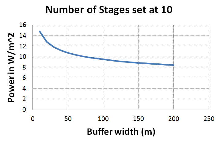
But let's say that we want to push the limits even further? What if we use more space for the friction buffers? I set the number of friction buffers as constant at 10, and then looked at the impact.
Here, you can see that using more area is much less effective than adding more friction buffer stages (although it would be easier). Of course, at some point, increasing the outer radius more will increase the circumference so much that it won't actually save you any more material. It's difficult to imagine the friction buffers would make sense at any significant multiple of the radius. So what I've described here is definitely in the neighborhood of the optimal configuration that a space-faring civilization would pick.
These calculations have really helped me zero in on what this type of civilization would look like. For what it's worth, the solar panels on the International Space Station produce about 120 kW. This amount of power would sustain the rotation of about 30,000 square meters of land in a gravitational balloon. Even at a (somewhat) rural population density of 250 people per square km, this would support about 8 people.
Even in the most extreme circumstances, the power needed to keep these artificial gravity structures rotating wouldn't be that much compared to the other energy needs of the people. At least that's the case if you used the above 16 friction buffer layout. Inhabitants might opt to use fewer at the gain of more energy. Either way, the point I'm making is that these calculations clearly show that the energy wouldn't be a deal breaker.


No comments:
Post a Comment